" - To Build a Twisted
Bridge - "
Carlo
H. Séquin
Computer
Science Division, EECS Department
University
of California, Berkeley, CA 94720
E-mail: sequin@cs.berkeley.edu
Abstract
|
This
is a follow-up on a discussion at the 1999 Bridges conference; it is a
topological / geometrical study of how the structure of a Moebius band
might be applied to bridges and/or buildings, with the possibility of creating
an intriguing construction on the Campus of Southwestern College, to commemorate
the series of annual Bridges conferences started in 1998.
|
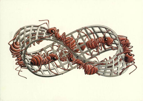
Fig.
1: M.C. Escher's "Moebius Strip II" © 2000 Cordon Art B.V.,
Baarn, Holland [3].
1. Introduction
At the
Bridges'99 conference, Jason Barnett gave an inspiring presentation "A
Bridge for the Bridges" [1]. He showed scale models of
spaces reminiscent of Escher structures that combine many different perspectives
in surprising ways. However, Barnett's buildings were realized in 3-space
and were designed to be readily navigable by human observers. In that session,
the idea was put forward that it might be desirable to construct a monument
on the Campus of Southwestern College commemorating the series of annual
Bridges conferences. Given the interests of the typical conference participant,
such a structure might well be Escher-like or reminiscent of the shapes
of Klein bottles or Moebius bands. Perhaps - and most fittingly - such
an intriguing shape might be applied to some form of pedestrian bridge
crossing a little creek or connecting two tall buildings. Inspired by those
discussions, this paper investigates several ways in which the structure
of a Moebius band could be imposed onto a functional bridge (Section
2) or onto a habitable and usable building (Section 3).
We conclude with some Moebius structures that have a purely aesthetic purpose
(Section 4).
The title
of this treatise pays homage to a delightful science fiction short story
by Robert A. Heinlein, "-And He Built a Crooked House-" [4],
in which an architect builds a 4-dimensional house in the shape of a hypercube.
After an earthquake, the house traps its occupants who are then doomed
to run around in the 3-dimensional surface of this structure. Contrary
to this unfortunate outcome, our focus is on finding structures that are
not only conceptually intriguing, but also sound and of practical use.
2. Moebius Bridges
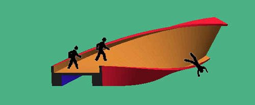
The
first idea that comes to my mind when I hear the term "Moebius" is that
of a belt twisted through 180 degrees. However, if this idea is applied
in a straightforward manner to the construction of a bridge, we end up
with a surface that is difficult to walk on; after crossing less than half
the length of the span, travellers would slide off the bridge (Fig.
2 ). Thus the first task is to look for modifications of the basic
concept to create a more or less level walking surface along the whole
length. After that I will explore the possibilities of transforming the
topology of a closed Moebius band into a shape that can serve as a bridge.
2.1.
Twisted Surfaces You Can Walk On
The
first and fundamental challenge is to find geometries that are clearly
twisted, but on which one can still walk, and which will even admit wheelchairs,
i.e., surfaces that have a continuous strip of a nearly horizontal surface
along the whole span of the bridge. A first inspiration may come from ruled
surfaces, in particular from a single-shell hyperboloid, which exhibits
a rather twisted look, but can be composed entirely of a bundle of straight
lines. The wish to keep a more or less "level path" across the chasm to
be bridged implies that we also maintain horizontal tangents in the lateral
direction. We may model these constraints with a Bézier patch that
gives us sufficient degrees of freedom (Fig. 3).
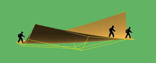
Fig.
3: A longitudinal twist can be simulated with a suitably distorted
Bézier patch.
Using
five control points in the lateral direction, allows us to create a "flat"
zone of adjustable width. Along the length of the bridge span this flat
zone shifts from one edge of the patch to the other, i.e., at one end of
the bridge the right-hand wall is pulled high, and at the other end the
left-hand wall. This will create the impression that the slab has been
flipped through almost 180 degrees. In the longitudinal direction, three
or four rows of control points are sufficient to define the transition
of the cross section from one end to the other, and perhaps to impose a
slight arching of the bridge for stability and for aesthetic purposes.
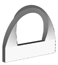
Contemplation
of the shape in Figure 3 makes one realize that the main
reason that travelers do not slide off this bridge is the fact that its
cross section is a "hollow" C-shape which offers a spot with a horizontal
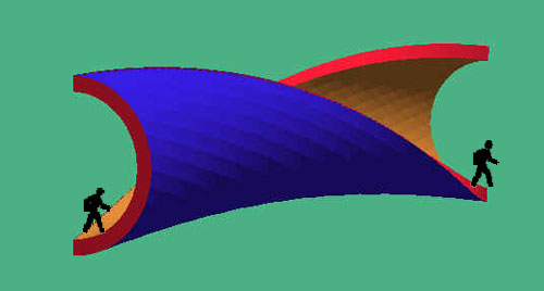
tangent for all of its orientations. We can exploit this idea more directly
by sweeping a semicircular cylindrical element along the arch of the bridge.
We can twist this cross section through 180 degrees and still maintain
along its whole length a continuous path with a horizontal lateral tangent
(Fig. 4). It should be noted that on such a surface
one could walk either on the inside or on the outside of the C-shape; in
the latter case we would twist the cross section in such a way that, in
the middle of the bridge, the opening of the "C" points downwards. However,
for a large portion of the span, travellers may not even realize that they
are walking on an open C-profile; it may just feel like walking along the
top of a giant cylinder. I believe the sense of "twistiness" of the bridge
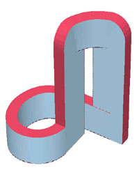
would be mostly absent in this option. In Figure 4, I
show my preferred solution, where the profile is oriented like a "U" at
the mid-point, and in which travellers across the bridge are naturally
sheltered most of the way. Of course, towards the ends of the span, some
railings must be added for safety.
2.2.
Closing the Moebius Loop
To shape
such a twisted bridge surface into a closed Moebius band, we have to somehow
form an end-to-end loop and close it off with the appropriate orientation.
This closure could occur in three fundamentally different ways: below the
walkway, and thus symbolically acting as the foundation or support for
the walkway (Fig. 5a); above the walkway, as a large
arch from which the walkway could be "suspended" in some way (Fig.
5b); and, third, besides the walkway -- perhaps forming a separate
alternative walkway.
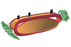
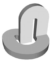
The first
alternative leads to a rather straightforward implementation (Fig.
5a). This is just a simple, singly-twisted Moebius band. All the twist
is in the "return path" and support structure. Aesthetic goals and engineering
functionality might be nicely combined if the "bulge" created by the twisting
slab where it passes through its vertical orientation is made to touch
the middle of the horizontal portion of the slab that serves as the actual
bridge; it can then act as center support and thus allows the slab to be
thinner. Access to the bridge surface is also easy in this configuration,
since the slab turns downwards at both ends of the span. Light-weight,
transparent-looking "on-ramps" would connect the main structure to the
slopes of the trench to be bridged.
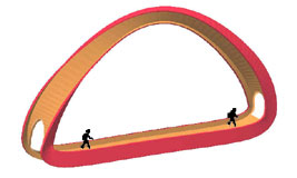
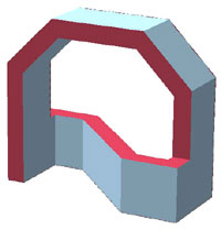
The second
alternative develops from an upside-down version of the first. The "roll"
of the slab through its vertical orientation can now serve as a robust
suspension arch from which the walkway could be suspended with many thin
steel cables (Fig. 5b). One difficulty with this arrangement
is that the travellers will now walk on the "inside" of the structure,
and access to this surface has to be provided in some way. One solution
is to cut openings through the band itself at both ends of the horizontal
bridge section where the band turns upward. This will produce two doorways,
each framed by two columns formed by the outer flanges that support the
slab.
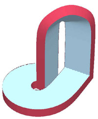
Another
possibility is to bend the twisted surface laterally away from the main
walkway, thereby giving straight access onto the walkway. If the walkway
happens to be in a concavity of the main Moebius band (Fig.
4), then such a bending away to the sides is reminiscent of the swept
C-section ribbon sculptures of Brent Collins [2] in which
he aims to orient the C-shaped profile in such a way that its opening always
points away from the bending direction of the space curve, i.e., in the
negative normal direction of its Frenet frame. This results in a ribbon
surface of consistently negative curvature. However, a C-shaped profile
is clearly two-sided; it has an inside and an outside, and it can therefore
not readily be closed into a single-sided Moebius configuration. To achieve
this goal, we may gradually straighten out the C-profile into a flat slab,
which can then readily be connected back-to-front. This may again lead
to a configuration where the return path forms a suspension arch (Fig.
6).
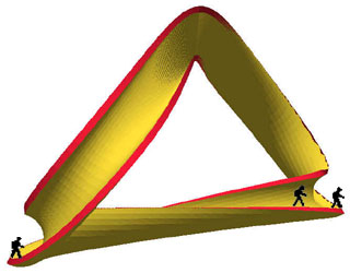
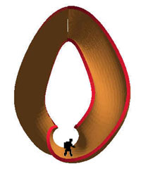
Fig.
6: Closing the Moebius loop through a non-planar
space curve and varying its cross section,
(a) side view, and (b) view from one end looking down the walkway.
2.3.
Function Follows Form
So far,
all my constructions started with a functional walkway, then I tried to
close those twisted surface pieces into Moebius loops. Now I will start
from various geometrical Moebius configurations and then see how such a
shape might serve as a bridge. For this purpose, the work of M.C. Escher
serves as a great source of inspiration. In "Band van Möbius II" he
draws a simply twisted band in grid form that serves as a climbing structure
for nine ants (Fig. 7a). Let's study this shape and see
in which way it may be turned into a bridge. The portion facing backwards
in Figure 7a offers a reasonably flat surface that runs
most of the length of the whole object. It may serve as a walking surface
if the whole structure is oriented suitably in space and the twist is redistributed
somewhat differently around the loop (Fig. 7b).
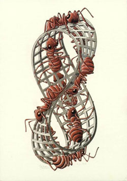
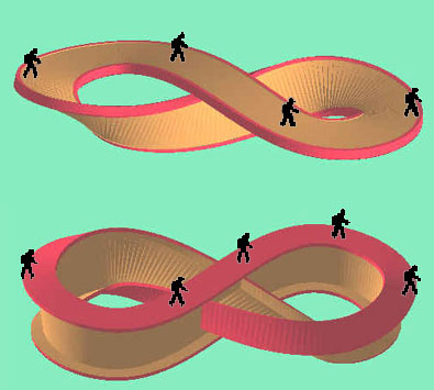
Fig.
7: Use of the geometry of Fig.1 [3]
(a) for a bridge design, (b) by walking on part of the surface, and (c)
by walking on the widened edge of the Moebius strip.
Alternatively,
we could orient this surface downward and thereby turn the front-facing
portion of the rim of this object into the proper orientation so that it
could be walked on. The edge would have to be widened to make a safe and
comfortable walkway. This could be accomplished by making the whole band
much thicker, or by using it only as a support structure and by adding
a perpendicular flange onto it to serve as the actual walking surface.
Since this flange would of course run around the whole Moebius band, it
would convert the cross section of the band into that of an I-beam. Upon
closer inspection of Escher's object, it appears that the backward-facing
edge of this same part of the Moebius band has a somewhat larger longitudinal
extent than the front-facing rim, and might thus be more suitable to serve
as a bridge over a trench or ravine of a given width. But as is evident
from (Fig. 7b), some part of that edge is obstructed
by the crossing slab that we originally considered as the walking surface.
This can easily be remedied if we a modify the structure so that it intersects
itself at the central point (Fig. 7c). This self-intersection
may also increase the overall strength of the whole structure.
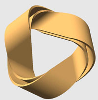
M.C. Escher
also drew another Moebius band that exhibits three-fold symmetry and which
has a built-in twist of 540 degrees (Fig. 8a). This basic
arrangement also appears in the familiar recycling symbol (Fig.
8b) created by Container Corporation of America during Earth Day 1970.
A contest for graphic art students to design a symbol representing paper
recycling attracted over a thousand entries which were judged at the Aspen
Institute for Humanistic Studies. The winning entry submitted by Gary Anderson,
an art student at U.C. Berkeley, was modified by William Lloyd into the
well-known "chasing arrows" design.
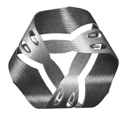

Fig.
8: (a) M.C. Escher's "Moebius Strip I" © 2000 Cordon Art B.V.,
Baarn, Holland [3]; (b) recycling symbol with same three-fold
symmetry.
Sometimes
one encounters a modified form of the recycling symbol that has an overall
twist of only 180° (Fig. 9a). We will explore the
usefulness of this structure to create a pedestrian bridge. We follow the
possibility shown in Figure 7a of walking on the edge
of the Moebius band, rather than on its flat surface. Figure
9b shows how one inner section of the edge might be used as a walkway.

However,
there is an intriguing possibility to also use the "suspension arch" as
a secondary walkway. Reminiscent of a strongly arched bridge in a Japanese
tea gardens, steps may lead up on the outer edges of the suspension arch.
On the very top, where the mostly vertically oriented band needs to flip
over to make the desired Moebius connection, a flat spot might be created
suitable for a small observation platform.
3.
Moebius Buildings
In 1992
Peter Eisenman designed a Moebius building (Fig. 10a).
One gets the impression, that this particular building was purely a mental
exercise in the strictest tradition of an architectural design paradigm
known as "function follows form." It is not immediately clear how this
particular form can be structured internally to make a set of convenient
and usable floors and suites. Another "Moebius Haus" was conceived by Van
Berkel & Bos who try to capture the endless figure-8-type movement
possible in this topo-logy in some internal unstructured space (Fig.
10b).
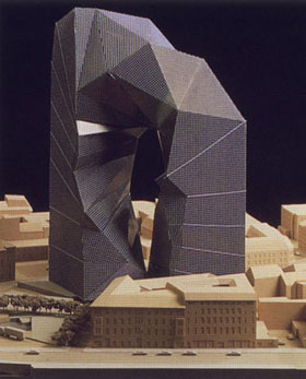
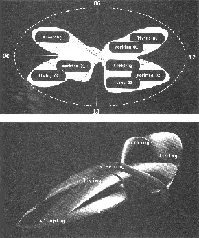
Fig.
10: Moebius buildings: (a) a proposal by Peter Eisenman, (b) a concept
by Van Berkel & Bos.
3.1.
Form Follows Function
For
this study we assume that the client wants a reasonably traditional office
building, say, for a Mathematics Institute, but one that clearly reflects
the shape of a Moebius band. We are not interested in just a thin mathematical
surface, but in a prismatic structure of substantial volume that exhibits
the desired "twist." We start our analysis with a cubic module of 32 feet
on a side. This is large enough to accommodate two 12 foot deep offices
and an eight foot corridor "across" the building, and two stories in the
vertical dimension. We first will explore ways of stacking these useful
modules so that the essence of a Moebius strip is conserved, i.e., if we
follow along one face of the prismatic toroid, we expect that it will take
more than one loop around the ring before we come back to the starting
point and that we will visit "other" faces of the prismatic structure on
this path.
Three
such cube modules in sequence can form either a straight row or a small
symmetrical L-shape. Four cubes in sequence can form a planar L-shape with
one leg twice as long as the other or a planar "Z"/ "S" jog structure.
But they can also form a twisted, 3D Z-structure, which may appear as a
right-handed or as a left-handed version. It is the appearance of this
twist element that carries a path on the surface of the prismatic structure
from "one face" to "another". The simplest "twisted" loop can be built
from just ten such cube-modules (Fig. 11a). A path on
one of the prism surfaces incurs a twist of 90 degrees on every loop around
the structure. It thus takes four loops to come back to the starting point,
and during this traversal we will have visited all the exposed cube faces
on the whole structure.
But let's
assume that the client wants a "normal" Moebius band, in which we return
to the starting point after only two revolutions. There are many basic
configurations in which two twist elements can be arranged so that their
effect adds up, rather than cancels out, and so that the total prismatic
twist around the loop becomes 180 degrees.
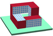
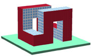
One configuration
is shown in Figure 11b. The twist elements have been
placed at the corner of the loop and have been stretched in the vertical
direction so that they form entrances into the courtyard / atrium of the
building. Another possibility, shown in Figure 11c,
introduces a 3D crossing in the form of a sky-bridge in order to close
the loop with a 180o twist. Alternatively, this bridge can be straightened
out, while the connecting path at ground level becomes S-shaped (Fig.12a).
Figure
12b gives an impression what an actual building, derived from this
basic configuration, might look like.
3.2.
Function Follows Form.
Now
that we have seen that it is indeed possible to create Moebius shapes from
rather conventional building elements, we might want to make the Moebius
shape more apparent. First, and foremost, we would like to use a more band-like
structure, i.e., the aspect ratio of the rectangle swept along the loop
should be at least 2:1. In addition, we want to make the small sides and
the long sides of the cross section visibly distinct by using different
materials. The large faces could be made from glass and steel, which would
be natural for the window fronts, and the narrower faces could be made
from concrete, or could be covered with dark, opaque glass.
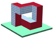
However,
just sweeping a 32' by 64' cross section along a circle with continuous
twist (Fig. 13a) will not lead to a practical building
geometry. Figure 13b shows a modification of the basic
Moebius shape in which one end has been squared to form the base of a building
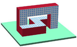
and the rest of the loop is connected to it with two right-angle turns.
This shape can be further deformed until it resembles the bridge structure
of Figure 12b with an S-shaped return path underneath,
but now the return section stands on its small edge (Fig.
13c). As a further refinement, the impractical wide span of the bridge
can be shortened, by narrowing the turns in the S-shaped building section
underneath.
Now it
is time to look more closely at the internal organization and the resulting
requirements for the surfaces of these structures. Clearly the more lightly
colored vertical walls of the S-shape should be in glass, since they are
natural window surfaces. The narrow faces of the prism could then be kept
fairly opaque. To enhance the visual difference between the two types of
surfaces even further, the narrow surfaces could also be reshaped into
wedges, which would show off the Moebius property most dramatically. On
top of the S-structure, where the wedge runs horizontally as a "roof,"
it could hide air-handling units, and along the vertical edges of the two
towers it could accommodate fire stairs or elevator shafts (Fig.
15d). The problem with the structure in Figure 13c
is that this opaque face or wedge runs on the sides of the bridge on the
facades where one would prefer to have a set of good windows; this prime
real-estate should not be obscured for the purpose of maintaining continuation
of the Moebius edge. In Figure 14, I explore a different
way to work around this problem by reversing the roles of the wide and
narrow sides of the swept cross section.
In Figure
14a I started with a dramatic vertical loop cut from a 32' thick slab
that has plenty of good window spaces on both sides. The narrow Moebius
edge runs vertically at the ends of the floors in the two towers and also
sweeps over the top of the building. Figure 15 illustrates
how the space in this prominent arch can be put to good use and provide
much office space with generous windows. To make the desired Moebius closure
for the overall structure, we need to connect the front side of one tower
with the backside of the other. This can be achieved with a spiral loop
formed by a low horizontal building branch (Fig. 14a).
In our envisioned Math Institute, this part could accommodate public functions
such as the class-rooms, the library, the cafeteria, and the reception
area. The latter three functions can make good use of skylights to accommodate
a glass roof as the logical continuation of the glass facades of the main
building loop. The class rooms could be placed in the lower story or underground.
Thus the mostly window-less Moebius edge, that needs to run around the
horizontal faces of this lower part of the building, could lie just slightly
above ground level, where vertical windows can most easily be traded off
for copious skylights.
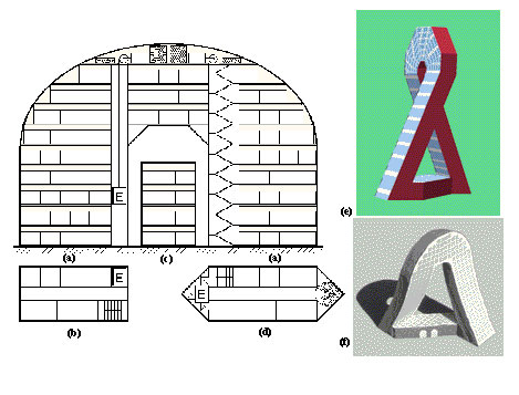
Fig.
15: (a) Elevations, and (b) floor plans of the arch in Fig.
14a; (c) cross section of an "on-edge" branch of the basic rectangular
profile, e.g., as used in Fig. 14c; (d) a variant of
the profile with wedges at the ends. (e) and (f) two different views of
another use of such an arch in a tall building with slanted towers.
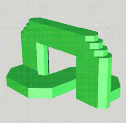
The bottom
portion of the structure in Figure 14a is rather larger.
We can reduce its area by angling the two towers at 90 towards each other.
This could change the originally semi-circular slab at the top into a conical
shape (Fig. 14b) - a structure that might be difficult
to build and to outfit with elevators all the way to the top floor. Also
it is not clear how usable the assignable floor spaces would be in this
conical part of the building. Thus the concept is further developed in
Figure
14c. The conical top section has been replaced with just a short, bent
bridge with perfectly level floors and vertical walls. In contrast to the
bridges in Figure 13, the elongated cross section is
now swept in a vertical orientation through this part. This keeps the Moebius
edge on top and bottom, and maintains good window fronts on the vertical
faces. This same approach can also be used at the bottom end of the building.
The spiral connection between the two towers can be made with a vertically
oriented sweep, providing much good window front (Fig. 14c).
One possible
drawback with this geometry is that it may lead to rather tall buildings.
Even if the swept rectangular cross section is reduced to only 30' by 60',
an arch tall enough to loop over its own cross section put on edge would
be at about 140' tall. Still I believe this arched configuration of the
sweep has a lot of potential and can be shaped into attractive and usable
buildings.
Figure 15e and 15f show
another way of closing this dominant arch into a Moebius loop. The legs
are bent forwards and backwards like the two leaning towers in the "Gate
of Europe" in Madrid. This spread must provide enough separation at the
bottom to accommodate a fairly direct connection between the back-side
of the front leg and the front-side of the back leg. Again this low, horizontal
portion would be provided with continuous skylights that offer dramatic
views of the arch 15 to 20 stories above.
4. Moebius Sculptures
A functional
bridge or building may be beyond the means that Southwestern College is
willing to expend on a commemorative construction. Perhaps a pure art object
is a viable alternative. In this section we explore the realm of artistic
Moebius bands and spaces.
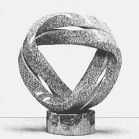
Keizo
Ushio [5] is a sculptor who has celebrated twisted band
structures in many different forms. While I am not sure whether he has
ever carved an elementary, singly-twisted Moebius band, he has created
doubly and triply twisted bands, and dozens of split Moebius bands (Fig.
16a,b). Often his Moebius strips are produced by a rectangular cross
section swept along a simple space curve with the proper twist so that
the "front" side of the slab connects to the "back" side after one travel
around the loop. Most often Keizo Ushio takes such a Moebius band only
as the starting point, and then adds extra drama to it by splitting it
along a center line.
In Keizo
Ushio's sculptures typically the large dimension of a wide band is split
down the middle, resulting in two nearly square prismatic shapes travelling
side by side. This is a natural approach for sculptures carved from stone.
Even Escher's triply twisted Moebius band is split in the same way (Fig.
8a). However, for different materials, say, steel, it may be just as
natural to split the band from its narrow sides, leading to two even thinner
cross sections travelling "on top of one another" (Fig.
16c). This has the intriguing effect of creating a much more pronounced
enclosed space between the two parts. That space itself now has the topological
properties of a Moebius band, even though its bounding material band is
orientable, i.e., double-sided (one side faces the Moebius space and the
other side is pointing outward). Since the major portion of this paper
is concerned with the creation of twisted Moebius spaces accessible to
humans, I will now focus on a sculpture that emphasizes the enclosed space
rather than its bounding material walls.
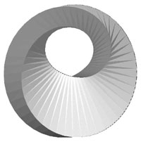
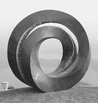
My proposed
"Moebius Space" sculpture is derived from a "split torus" in which the
cutting gap makes a 180 degree twist while sweeping around the torus. Since
this space is the intended focus of our attention, I have widened it and
also bulged it out to make it look more like a cave. To draw even stronger
attention to it, I have given its wall a shiny silvery color, while keeping
the outside of the torus from which it is carved in matte black (Fig.
17).
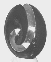
Fig. 17: The proposed "Moebius
Space" sculpture, (a) computer-generated view, and
(b) a physical maquette made with a Fused Deposition Modeling machine.
5. Conclusions and
Acknowledgments
The single-sided Moebius
loop is a fascinating geometrical shape and leads readily to a plethora
of aesthetically pleasing sculptures. But beyond this purely aesthetic
value, the Moebius form can also be transformed into practical functions
such as buildings or bridges. Given the tight linking of arts and mathematics
exhibited in the Moebius shape, it would be a very fitting symbol for a
commemorative construction for the Bridges Conferences at Southwestern
College in Winfield, Kansas.
This work was partially
supported by the National Science Foundation under a research grant to
study the designer/fabricator interface for rapid prototyping. The synthetic
figures and sculpture models have been constructed with SLIDE, a modeling
and rendering system built by Jordan Smith [6] and Jane
Yen.
References
-
J. F. Barnett:
"A Bridge for the Bridges," Bridges 1999, Special Session VI, Aug.1, 1999.
-
Brent Collins:
"Merging Paradigms," Bridges 1999, Conference Proceedings, pp 205-210.
-
M. C. Escher;
with permission from Cordon Art B.V., Baarn, Holland. All rights reserved.
-
R. A. Heinlein:
" -- And He Built a Crooked House --, " Berkeley Publishing
Group, NJ.
-
K. Ushio,
sculptor, homepage:
http://www2.memenet.or.jp/~keizo/
-
J. Smith:
"SLIDE: Scene Language for Interactive Dynamic Environments,"
http://www.cs.berkeley.edu/~ug/slide/
HOME
|